
How to Choose Multi Pair Instrumentation Cable?
Choosing a Multi Pair Instrumentation Cable is not simply a matter of picking the right number of pairs. The cable must carry control or measurement signals reliably through its actual installation environment. A mismatch in conductor size, insulation, or shielding can create noise, complicate termination, or shorten service life. Small details matter.
Start by identifying the signal type, pair count, conductor gauge, and required electrical ratings. Then check the shielding design. Individual pair shields can help limit interference between circuits, while an overall shield may protect the cable from external electrical noise. Neither choice is automatically best. Nearby motors, variable-speed drives, and long cable runs can all affect signal quality, so consider the route as well as the equipment.
The outer jacket deserves equal attention. Temperature, moisture, sunlight, chemicals, and mechanical wear may influence which material is suitable. Review the manufacturer’s datasheet for operating limits and construction details, and confirm that they fit the site conditions. A specification can look complete yet leave practical questions unanswered.
Before ordering, compare the cable’s dimensions with available conduit, glands, and termination space. Check bend radius and installation requirements, too. These details are easy to overlook. They can still cause delays.
A careful selection balances electrical performance, environmental protection, and installation needs. This guide explains how to assess those factors and compare options. Not every project has a perfect answer; documenting assumptions can make the final choice more dependable.
Define the Application and Operating Environment
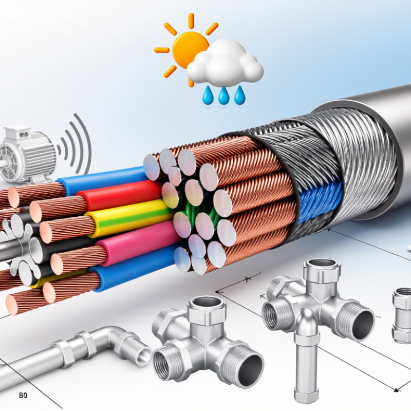
Before choosing a multi-pair instrumentation cable, define what it will carry and where it will run. Low-level sensor signals may need stronger protection from electrical noise than ordinary control circuits. A cable beside variable-speed drives, motors, or fluorescent lighting can pick up interference. Damp areas, outdoor trays, and washdown zones add different concerns. Match the cable jacket and construction to the actual exposure, not just the room’s average temperature.
Check the number of pairs, conductor size, and total cable distance against the instrument and control-system requirements. Long runs can increase signal loss, while tight bends and repeated movement can damage conductors or shielding. A shield may help reduce noise, but its grounding method should match the system design. Do not assume every installation needs the same shield arrangement. Review the equipment documentation and site wiring practices, then confirm that the cable’s temperature rating covers both normal operation and nearby heat sources.
Tips: Walk the planned route before specifying the cable. Look for sharp edges, standing water, and power cables sharing the tray. Record these details. It is easy to miss one awkward bend, and that small oversight can complicate installation later.
Match Pair Count, Conductor Size, and Electrical Requirements
Choose pair count from the actual signal list, not the cable’s advertised maximum. A 12-pair cable may suit a control panel with spare circuits, but unused pairs still add bulk and termination work. Sketch the route and label each signal before ordering. Leave room for future circuits, but do not let “extra capacity” become an excuse for a cable that will not fit the tray.
Conductor size should follow current, distance, voltage drop, and terminal limits. IEC 60228’s resistance data lists a maximum of 12.1 Ω/km for 1.5 mm² class 2 copper conductors, versus 7.41 Ω/km for 2.5 mm² conductors. That difference matters on a long run carrying low-level signals. Check operating voltage, expected temperature, shielding, and pair-to-pair crosstalk requirements too. A larger conductor is not automatically better; it may exceed terminal capacity or increase cable diameter. I still verify the complete cable data sheet against the installation conditions.
Tips: Count spare pairs, calculate loop resistance, and confirm terminal sizes. Keep a little margin. Recheck the route’s bend radius before approving the drum length.
How to Choose Multi Pair Instrumentation Cable? - Match Pair Count, Conductor Size, and Electrical Requirements
| Selection example | Pair count | Conductor size | Approx. conductor resistance at 20°C | Shielding approach | Typical fit and checks |
|---|---|---|---|---|---|
| Compact signal run | 2–4 pairs | 22 AWG (0.64 mm) | 16.14 Ω/1000 ft (52.9 Ω/km) per conductor | Individual pair shields for sensitive or low-level signals; overall shield where needed | Useful for short instrument connections. Check loop resistance, signal level, and interference exposure. |
| General-purpose control and measurement | 6–12 pairs | 20 AWG (0.81 mm) | 10.15 Ω/1000 ft (33.3 Ω/km) per conductor | Overall shield for shared protection; individually shielded pairs when pair-to-pair coupling is a concern | A common balance of cable size and resistance. Confirm pair assignment, grounding method, and required cable listing. |
| Longer run or higher loop-resistance sensitivity | 2–12 pairs | 18 AWG (1.02 mm) | 6.385 Ω/1000 ft (20.9 Ω/km) per conductor | Select pair and/or overall shielding according to noise conditions and signal type | Lower conductor resistance can help on longer runs. Verify voltage drop, termination compatibility, and installation space. |
| High-density instrument wiring | 16–24 pairs | 22 or 24 AWG (0.64 or 0.51 mm) | 22 AWG: 16.14 Ω/1000 ft; 24 AWG: 25.67 Ω/1000 ft per conductor | Individually shielded pairs can improve pair isolation; confirm overall shield and drain-wire construction | More pairs reduce the number of separate cable runs but increase cable diameter and termination effort. Check tray fill and bend radius. |
| Low-level analog or noise-sensitive signals | As required by the I/O schedule | Typically 20–22 AWG; confirm circuit needs | Use the selected conductor’s resistance and actual route length for calculations | Twisted pairs with individual shields are often considered; follow the instrument and site grounding design | Check capacitance, pair balance, separation from power cables, and the required shield termination at each end. |
| Outdoor or hazardous-area installation | Based on circuit count and spare-pair policy | Choose by resistance, mechanical needs, and terminal compatibility | Refer to the cable manufacturer’s verified data for the exact construction | Specify shielding and any armor or protective jacket separately | Confirm temperature range, moisture and UV resistance, flame performance, approvals, and area classification requirements. |
Selection note: Resistance figures are approximate copper-conductor values at 20°C; actual cable values vary with conductor construction and temperature. Pair count, capacitance, voltage rating, shielding, jacket, and approvals are construction-specific. Verify the cable datasheet and applicable project requirements before ordering.
Select Insulation, Jacket, and Cable Construction
How to Choose Multi Pair Instrumentation Cable?
Select Insulation, Jacket, and Cable Construction
Start with the signal and the installation environment. Polyethylene insulation can help reduce capacitance, while cross-linked polyethylene may suit applications requiring higher temperature performance. PVC is often a practical choice, but confirm its temperature and chemical-resistance limits. Check the cable’s rated voltage and operating range against the actual equipment requirements. Details matter.
The jacket must withstand what the cable will encounter: moisture, sunlight, abrasion, or contact with oils. A jacket that works indoors may age poorly outdoors. For construction, twisted, color-coded pairs make identification and termination easier. Individual pair shields can limit crosstalk between sensitive circuits; an overall shield may help reduce external interference. Some designs use both, adding protection but also bulk and stiffness. Consider routing space and bend radius before choosing.
In the field, I would check the datasheet for capacitance, shielding details, and temperature ratings, then compare them with the instrument manual. Confirm how the shield should be terminated; grounding practice can affect noise performance. A drain wire can simplify shield continuity, but it does not replace correct installation. I have seen selection decisions focus heavily on shielding while overlooking jacket exposure. That is easy to miss. Choose the construction for the full cable route, not just the control cabinet.
Choose Shielding and Grounding for Noise Control
For multi-pair instrumentation cable, match the shield to the noise environment. A foil shield with a drain wire offers broad coverage and straightforward termination. A braid can provide durable coverage where the cable flexes or faces physical wear. In areas with strong interference, individually shielded pairs can reduce crosstalk between sensitive signals. They also add bulk and cost. More shielding is not always better.
Grounding matters just as much. Connect the shield according to the instrument and system design; a common approach is grounding one end to limit low-frequency ground-loop currents. In some high-frequency installations, grounding both ends may improve noise performance, but it can create unwanted current paths. Check equipment documentation and site practices before terminating. That rule is not universal, and assuming it is can lead to noisy readings. Keep shield connections short and secure, and separate signal cable from motors and power conductors where practical.
Tips: Check whether the cable has an overall shield, pair shields, or both. Label each shield before installation. A quick continuity check can catch a loose drain wire. During commissioning, compare readings with nearby equipment on and off; small changes can reveal interference.
Verify Standards, Compatibility, and Installation Conditions
Choosing multi pair instrumentation cable starts with the project specification, not the pair count alone. Confirm the required standards and approvals for the site, then check conductor size, insulation temperature rating, voltage rating, and shielding construction. Requirements can differ between industrial plants, outdoor routes, and control rooms. Do not assume that a familiar cable description guarantees compliance; compare the actual datasheet with the project documents.
Compatibility matters at both ends. Check the instrument’s signal type, expected impedance, and allowable cable capacitance. For low-level signals, suitable shielding and a clear grounding plan can reduce interference. Match the number of pairs to current and planned circuits, while leaving practical room for termination. A cable may fit the electrical specification yet prove awkward inside a crowded junction box. That detail is easy to miss. Review connector space and bend radius before ordering.
Tips: Walk the proposed route. Note heat, moisture, sunlight, chemicals, and possible mechanical damage. Confirm whether the cable will run in conduit or a tray, and keep separation from power cables where the design requires it. Check the specified fire performance and installation limits. If any requirement is unclear, ask the responsible engineer or supplier to confirm it in writing. Small assumptions can become costly rework.
